본문 바로가기
임베디드

Linux CAN Network - CAN드라이버와 SocketCAN

by I!i어★떤☆날★에Ι!i 2022. 11. 5.
반응형

Linux에서 CAN driver를 사용할 일이 생겨서, CAN driver관련 문서를 공부하고 있다. 그 중, 리눅스 커널의 can 설명 파일을 보면서, 정리 차원에서 여기에 다시 작성해 보았다.


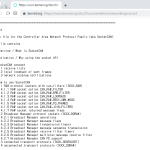
이 글은 다음의 리눅스 커널 CAN 네트워크 문서 내용이다.

https://www.kernel.org/doc/Documentation/networking/can.txt
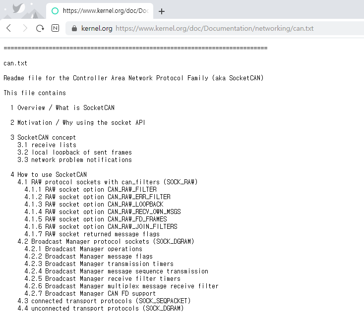


socketCAN
socketCAN


1. Overview / What is SocketCAN
--------------------------------

SocketCAN 패키지는 Linux용 CAN 프로토콜(Controller Area Network)의 구현입니다. CAN은 자동화, 임베디드 장치 및 자동차 분야에서 널리 사용되는 네트워킹 기술입니다. character devices를 기반으로 한 Linux용 CAN 구현이 있는 반면, SocketCAN은 Linux 네트워크 스택인 Berkeley 소켓 API를 사용하고 CAN 장치 드라이버를 네트워크 인터페이스로 구현합니다. CAN 소켓 API는 네트워크 프로그래밍에 익숙한 프로그래머가 CAN 소켓 사용법을 쉽게 배울 수 있도록 TCP/IP 프로토콜과 최대한 유사하게 설계되었습니다.


2. Motivation / Why using the socket API
----------------------------------------

SocketCAN 이전에 Linux용 CAN 구현이 있는데 왜 다른 프로젝트를 시작했는지에 대한 질문이 생깁니다. 대부분의 기존 구현은 일부 CAN 하드웨어용 장치 드라이버로 제공되며 문자 장치를 기반으로 하며 비교적 작은 기능을 제공합니다. 일반적으로 컨트롤러 하드웨어와 직접 주고받는 raw CAN 프레임을 위한 Character devices 인터페이스를 제공하는 하드웨어 전용 장치 드라이버만 있습니다.
프레임 대기열 및 ISO-TP와 같은 상위 레벨 전송 프로토콜은 사용자 공간 애플리케이션에서 구현되어야 합니다. 또한 대부분의 문자 장치 구현은 직렬 인터페이스와 유사하게 한 번에 장치를 여는 단일 프로세스만 지원합니다. CAN 컨트롤러를 교체하려면 다른 장치 드라이버를 사용해야 하며 종종 애플리케이션의 많은 부분을 새 드라이버의 API로 작성해야 합니다.

SocketCAN은 이러한 모든 한계를 극복하도록 설계되었습니다. 사용자 공간 응용 프로그램에 소켓 인터페이스를 제공하고 Linux 네트워크 계층을 기반으로 하여 제공된 모든 대기열 기능(queueing functionality)을 사용할 수 있도록 하는 새로운 프로토콜 제품군이 구현되었습니다. CAN 컨트롤러 하드웨어용 장치 드라이버는 Linux 네트워크 계층에 네트워크 장치로 등록되어 컨트롤러의 CAN 프레임이 네트워크 계층과 CAN 프로토콜 제품군 모듈로 전달될 수 있으며 그 반대도 마찬가지입니다.

 또한 프로토콜 패밀리 모듈(protocol family module)은 등록을 위한 전송 프로토콜 모듈(transport protocol modules)용 API를 제공하므로 원하는 수의 전송 프로토콜을 동적으로 load 하거나 unload 할 수 있습니다. 사실, CAN core 모듈만으로는 어떠한 프로토콜도 제공하지 않으며 최소한 하나의 추가 프로토콜 모듈을 로드하지 않고는 사용할 수 없습니다. 여러 소켓이 서로 다르거나 동일한 프로토콜 모듈에서 동시에 열릴 수 있으며 서로 다르거나 동일한 CAN ID에서 프레임을 수신/전송할 수 있습니다. 동일한 CAN ID를 가진 프레임에 대해 동일한 인터페이스에서 수신 대기하는 여러 소켓은 모두 동일한 수신 일치 CAN 프레임을 전달합니다. 특정 전송 프로토콜을 사용하여 통신하려는 응용 프로그램, 예: ISO-TP는 소켓을 열 때 해당 프로토콜을 선택하기만 하면 CAN-ID, 프레임 등을 처리할 필요 없이 애플리케이션 데이터 바이트 스트림을 읽고 쓸 수 있습니다.

사용자 공간에서 볼 수 있는 유사한 기능은 캐릭터 장치(character device)에서도 제공할 수 있지만 다음과 같은 몇 가지 이유로 기술적으로 부적절한 솔루션이 됩니다.

* 복잡한 사용법(Intricate usage)

   : 프로토콜 인수를 socket(2)에 전달하고 bind(2)를 사용하여 CAN 인터페이스와 CAN ID를 선택하는 대신 응용 프로그램은 ioctl(2)을 사용하여 이러한 모든 작업을 수행해야 합니다.

* 코드 중복(Code duplication)

  : 문자 장치는 Linux 네트워크 대기열 코드를 사용할 수 없으므로 CAN 네트워킹을 위해 해당 코드를 모두 복제해야 합니다.

* 추상화(Abstraction)

   : 대부분의 기존 문자 장치 구현에서 CAN 컨트롤러용 하드웨어 특정 장치 드라이버는 응용 프로그램이 작동할 문자 장치를 직접 제공합니다.
  이것은 char 및 block 장치 모두에 대해 Unix 시스템에서 최소한 매우 이례적인 일입니다. 예를 들어 직렬 인터페이스의 특정 UART용 문자 장치, 컴퓨터의 특정 사운드 칩, 하드 디스크 또는 테이프 스트리머 장치에 대한 액세스를 제공하는 SCSI 또는 IDE 컨트롤러가 없습니다.

 대신, 한편으로는 애플리케이션에 통합된 문자 또는 블록 장치 인터페이스를 제공하고 다른 한편으로는 하드웨어별 장치 드라이버를 위한 인터페이스를 제공하는 추상화 계층이 있습니다. 이러한 추상화는 위에서 언급한 장치의 tty 계층, 오디오 하위 시스템 또는 SCSI 및 IDE 하위 시스템과 같은 하위 시스템에서 제공됩니다.

  CAN 장치 드라이버를 구현하는 가장 쉬운 방법은 대부분의 기존 드라이버에서와 같이 (완전한(complete)) 추상화 계층이 없는 문자 장치로 사용하는 것입니다. 그러나 올바른 방법은 특정 CAN ID에 대한 등록, 여러 개의 열린 파일 설명자를 지원하고 이들 사이에 CAN 프레임을 다중화 또는 역다중화 ((de)multiplexing)하고, CAN 프레임의 (정교한(sophisticated)) 대기열을 제공하고, 등록할 장치 드라이버용 API입니다. 그러나 Linux 커널에서 제공하는 네트워킹 프레임워크를 사용하는 것이 더 이상 어렵지 않거나 더 쉬울 수 있으며 이것이 SocketCAN이 하는 일입니다.

  Linux 커널의 네트워킹 프레임워크를 사용하는 것은 Linux용 CAN을 구현하는 가장 자연스럽고 가장 적절한 방법입니다.


3. SocketCAN concept
---------------------

2장에서 설명한 것처럼 Linux 네트워크 계층을 기반으로 하는 사용자 공간 응용 프로그램에 소켓 인터페이스를 제공하는 것이 SocketCAN의 주요 목표입니다. 일반적으로 알려진 TCP/IP 및 이더넷 네트워킹과 달리 CAN 버스는 이더넷과 같은 MAC 계층 주소 지정이 없는 브로드캐스트 전용(!) 매체입니다. CAN 식별자(can_id)는 CAN 버스에서 중재에 사용됩니다. 따라서 CAN-ID는 버스에서 고유하게 선택되어야 합니다. CAN-ECU 네트워크를 설계할 때 CAN-ID는 특정 ECU에서 보내도록 매핑됩니다.
  이러한 이유로 CAN-ID는 일종의 소스 주소로 가장 잘 처리될 수 있습니다.

  3.1 수신 목록


  여러 애플리케이션의 네트워크 투명 액세스는 서로 다른 애플리케이션이 동일한 CAN 네트워크 인터페이스에서 동일한 CAN-ID에 관심을 가질 수 있는 문제로 이어집니다. 프로토콜 제품군 CAN을 구현하는 SocketCAN 코어 모듈은 이러한 이유로 여러 고효율 수신 목록을 제공합니다. 예를 들어 사용자 공간 응용 프로그램이 CAN RAW 소켓을 열면 원시 프로토콜 모듈 자체가 사용자가 요청한 SocketCAN 코어의 CAN-ID(범위)를 요청합니다. CAN-ID의 구독 및 구독 취소는 SocketCAN 코어에 의해 CAN 프로토콜 모듈에 제공되는 can_rx_(un)register() 기능을 사용하여 특정 CAN 인터페이스 또는 알려진 모든(!) CAN 인터페이스에 대해 수행할 수 있습니다(5장 참조).
  런타임 시 CPU 사용을 최적화하기 위해 수신 목록은 주어진 사용 사례에 대해 요청된 필터 복잡성과 일치하는 장치당 여러 특정 목록으로 분할됩니다.

  3.2 전송된 프레임의 로컬 루프백


  다른 네트워킹 개념에서 알 수 있듯이 데이터 교환 응용 프로그램은 변경 없이 동일하거나 다른 노드에서 실행될 수 있습니다(해당 주소 지정 정보 제외).

        ___  ___   ___                _____    ___
        | _ |  | _ |   | _ |                | _   _ |    | _ |
        ||A||  ||B||  | |C||               ||A| |B||   ||C||
        |__|  |__|   |__|                |____  |   |__|
           |      |        |                       |            |
        -----------------(1)- CAN bus -(2)---------------

  애플리케이션 A가 예(1)에서 수신하는 것과 동일한 정보를 예(2)에서 수신하도록 하려면 적절한 노드에서 전송된 CAN 프레임의 일종의 로컬 루프백이 필요합니다.

  Linux 네트워크 장치(기본적으로)는 미디어 종속 프레임의 전송 및 수신을 처리할 수 있습니다. CAN 버스의 중재로 인해 낮은 우선순위 CAN-ID의 전송은 높은 우선순위 CAN 프레임의 수신으로 인해 지연될 수 있습니다. 노드에서 올바른* 트래픽을 반영하려면 전송된 데이터의 루프백이 성공적인 전송 직후에 수행되어야 합니다. CAN 네트워크 인터페이스가 어떤 이유로 루프백을 수행할 수 없는 경우 SocketCAN 코어는 대체 솔루션으로 이 작업을 수행할 수 있습니다.
  자세한 내용은 6.2장을 참조하십시오(권장).

  루프백 기능은 CAN 애플리케이션에 대한 표준 네트워킹 동작을 반영하기 위해 기본적으로 활성화되어 있습니다. RT-SocketCAN 그룹의 일부 요청으로 인해 루프백은 각 개별 소켓에 대해 선택적으로 비활성화될 수 있습니다. 4.1장에서 CAN RAW 소켓의 소켓 옵션을 참조하십시오.

  * = (동일한) 노드에서 'candump' 또는 'cansniffer'와 같은 분석기 도구를 실행할 때 이것을 사용하는 것을 정말 좋아합니다.


  3.3 네트워크 문제 알림


  CAN 버스를 사용하면 물리적 및 미디어 액세스 제어 계층에서 여러 문제가 발생할 수 있습니다. 이러한 하위 계층 문제를 감지하고 기록하는 것은 CAN 사용자가 물리적 트랜시버 계층의 하드웨어 문제는 물론 중재 문제 및 다양한 ECU로 인한 오류 프레임을 식별하는 데 필수적인 요구 사항입니다. 감지된 오류의 발생은 진단에 중요하며 정확한 타임스탬프와 함께 기록되어야 합니다. 이러한 이유로 CAN 인터페이스 드라이버는 다른 CAN 프레임과 동일한 방식으로 사용자 애플리케이션에 선택적으로 전달할 수 있는 소위 오류 메시지 프레임을 생성할 수 있습니다. 물리 계층 또는 MAC 계층에서 오류가 감지될 때마다(예: CAN 컨트롤러에 의해) 드라이버는 적절한 오류 메시지 프레임을 생성합니다. 오류 메시지 프레임은 공통 CAN 필터 메커니즘을 사용하여 사용자 애플리케이션에서 요청할 수 있습니다. 이 필터 정의 내에서 (관심 있는) 오류 유형을 선택할 수 있습니다. 오류 메시지 수신은 기본적으로 비활성화되어 있습니다. CAN 오류 메시지 프레임의 형식은 Linux 헤더 파일 "include/uapi/linux/can/error.h"에 간략하게 설명되어 있습니다.


4. How to use SocketCAN
------------------------

TCP/IP와 마찬가지로 CAN 네트워크를 통한 통신을 위해 먼저 소켓을 열어야 합니다. SocketCAN은 새로운 프로토콜 패밀리를 구현하므로 socket(2) 시스템 호출에 대한 첫 번째 인수로 PF_CAN을 전달해야 합니다. 현재 선택할 수 있는 CAN 프로토콜은 원시 소켓 프로토콜과 브로드캐스트 관리자(BCM)의 두 가지입니다. 따라서 소켓을 열려면 다음과 같이 작성합니다.


    s = socket(PF_CAN, SOCK_RAW, CAN_RAW);

  또는

    s = socket(PF_CAN, SOCK_DGRAM, CAN_BCM);


각기. 소켓이 성공적으로 생성되면 일반적으로 bind(2) 시스템 호출을 사용하여 소켓을 CAN 인터페이스에 바인딩합니다(다른 주소 지정으로 인해 TCP/IP와 다릅니다. 3장 참조). 소켓을 바인딩(CAN_RAW)하거나 연결(CAN_BCM)한 후 소켓에서/에서 읽기(2) 및 쓰기(2)를 수행하거나 send(2), sendto(2), sendmsg(2) 및 recv* 대응물을 사용할 수 있습니다. 평소와 같이 소켓에서 작업을 수행합니다. 아래에 설명된 CAN 특정 소켓 옵션도 있습니다.

기본 CAN 프레임 구조와 sockaddr 구조는 include/linux/can.h에 정의되어 있습니다.

    struct can_frame {
            canid_t can_id;  /* 32 bit CAN_ID + EFF/RTR/ERR flags */
            __u8    can_dlc; /* frame payload length in byte (0 .. 8) */
            __u8    __pad;   /* padding */
            __u8    __res0;  /* reserved / padding */
            __u8    __res1;  /* reserved / padding */
            __u8    data[8] __attribute__((aligned(8)));
    };


(linear) payload data[]를 64비트 경계(boundary)에 정렬하면 사용자가 CAN payload에 쉽게 액세스 할 수 있도록 자신의 구조체와 공용체를 정의할 수 있습니다. 기본적으로 CAN 버스에는 주어진 바이트 순서가 없습니다. CAN_RAW 소켓에 대한 read(2) 시스템 호출은 구조체 can_frame을 사용자 공간으로 전송합니다.

   sockaddr_can 구조에는 PF_PACKET 소켓과 같은 인터페이스 인덱스가 있으며 특정 인터페이스에도 바인딩됩니다.

    struct sockaddr_can {
            sa_family_t can_family;
            int         can_ifindex;
            union {
                    /* transport protocol class address info (e.g. ISOTP) */
                    struct { canid_t rx_id, tx_id; } tp;

                    /* reserved for future CAN protocols address information */
            } can_addr;
    };


인터페이스 인덱스를 결정하려면 적절한(appropriate) ioctl()을 사용해야 합니다(예: 오류 검사가 없는 CAN_RAW 소켓).

    int s;
    struct sockaddr_can addr;
    struct ifreq ifr;

    s = socket(PF_CAN, SOCK_RAW, CAN_RAW);

    strcpy(ifr.ifr_name, "can0" );
    ioctl(s, SIOCGIFINDEX, &ifr);

    addr.can_family = AF_CAN;
    addr.can_ifindex = ifr.ifr_ifindex;

    bind(s, (struct sockaddr *)&addr, sizeof(addr));

    (..)


소켓을 모든(!) CAN 인터페이스에 바인딩하려면 인터페이스 인덱스가 0(영)이어야 합니다. 이 경우 소켓은 활성화된 모든 CAN 인터페이스에서 CAN 프레임을 수신합니다. 원래 CAN 인터페이스를 결정하기 위해 system call recvfrom(2)을 read(2) 대신 사용할 수 있습니다. 'any' 인터페이스에 바인딩된 소켓을 전송하려면 나가는 인터페이스(outgoing interface)를 지정하기 위한 sendto(2)가 필요합니다.

바인딩된 CAN_RAW 소켓에서 CAN 프레임 읽기(위 참조)는 struct can_frame 읽기로 구성됩니다.

    struct can_frame frame;

    nbytes = read(s, &frame, sizeof(struct can_frame));

    if (nbytes < 0) {
            perror("can raw socket read");
            return 1;
    }

    /* paranoid check ... */
    if (nbytes < sizeof(struct can_frame)) {
            fprintf(stderr, "read: incomplete CAN frame\n");
            return 1;
    }

    /* do something with the received CAN frame */


CAN 프레임 작성은"write(2) system call 을 사용하여 유사하게 수행할 수 있습니다.

    nbytes = write(s, &frame, sizeof(struct can_frame));


CAN 인터페이스가 '모든' 기존 CAN 인터페이스(addr.can_ifindex = 0)에 바인딩될 때 원래 CAN 인터페이스에 대한 정보가 필요한 경우 recvfrom(2)을 사용하는 것이 좋습니다.

    struct sockaddr_can addr;
    struct ifreq ifr;
    socklen_t len = sizeof(addr);
    struct can_frame frame;

    nbytes = recvfrom(s, &frame, sizeof(struct can_frame),
                      0, (struct sockaddr*)&addr, &len);

    /* get interface name of the received CAN frame */
    ifr.ifr_ifindex = addr.can_ifindex;
    ioctl(s, SIOCGIFNAME, &ifr);
    printf("Received a CAN frame from interface %s", ifr.ifr_name);


'모든' CAN 인터페이스에 바인딩된 소켓에 CAN 프레임을 작성하려면 나가는 인터페이스(Outgoing interace)를 확실히 정의해야 합니다.

    strcpy(ifr.ifr_name, "can0");
    ioctl(s, SIOCGIFINDEX, &ifr);
    addr.can_ifindex = ifr.ifr_ifindex;
    addr.can_family  = AF_CAN;

    nbytes = sendto(s, &frame, sizeof(struct can_frame),
                    0, (struct sockaddr*)&addr, sizeof(addr));


소켓(socket)에서 메시지를 읽은 후 ioctl(2) 호출로 정확한 타임스탬프(timestamp)를 얻을 수 있습니다.

    struct timeval tv;
    ioctl(s, SIOCGSTAMP, &tv);


타임스탬프(timestamp)는 1마이크로초의 분해능(resolution)을 가지며 CAN 프레임 수신 시 자동으로 설정됩니다.

  Remark about CAN FD (flexible data rate) support:


일반적으로 CAN FD의 처리는 이전에 설명한 예와 매우 유사합니다. 새로운 CAN FD support CAN 컨트롤러는 중재 단계와 CAN FD 프레임의 페이로드 단계 및 최대 64바이트의 페이로드에 대해 두 가지 다른 비트 전송률을 지원합니다. 이 확장된 페이로드 길이는 CAN_RAW 소켓과 같은 고정 8바이트 payload(struct can_frame)가 있는 CAN 프레임에 크게 의존하는 모든 커널 인터페이스(ABI)를 중단합니다. 따라서 예를 들어 CAN_RAW 소켓은 소켓을 CAN FD 프레임과 (legacy) CAN 프레임을 동시에 처리할 수 있는 모드로 전환하는 새로운 소켓 옵션 CAN_RAW_FD_FRAMES를 지원합니다(섹션 4.1.5 참조).


  The struct canfd_frame is defined in include/linux/can.h:

    struct canfd_frame {
            canid_t can_id;  /* 32 bit CAN_ID + EFF/RTR/ERR flags */
            __u8    len;     /* frame payload length in byte (0 .. 64) */
            __u8    flags;   /* additional flags for CAN FD */
            __u8    __res0;  /* reserved / padding */
            __u8    __res1;  /* reserved / padding */
            __u8    data[64] __attribute__((aligned(8)));
    };


struct canfd_frame과 기존 struct can_frame은 구조 내에서 동일한 오프셋에 can_id, payload길이 및 payload 데이터가 있습니다. 이것은 매우 유사한 다른 구조를 처리할 수 있습니다.
   struct can_frame의 내용이 struct canfd_frame에 복사되면 모든 구조 요소를 있는 그대로 사용할 수 있습니다. data[]만 확장됩니다.


struct canfd_frame을 도입할 때 struct can_frame의 데이터 길이 코드(DLC)가 길이 정보로 사용되었으며 DLC는 0 .. 8 범위에서 1:1 매핑이 있음이 밝혀졌습니다. 길이 정보를 쉽게 다루기 위해서 canfd_frame.len 요소는 0 .. 64의 일반 길이 값을 포함합니다. 그러므로 fd_frame.len과 can_frame.can_dlc는 동일하고 길이 정보와 no DLC를 포함합니다.


   CAN 및 CAN FD 가능 장치의 구별과 버스 관련 데이터 길이 코드(DLC)에 대한 매핑에 대한 자세한 내용은 6.6장을 참조하십시오.


  The length of the two CAN(FD) frame structures define the maximum transfer unit (MTU) of the CAN(FD) network interface and skbuff data length. Two definitions are specified for CAN specific MTUs in include/linux/can.h :

  #define CAN_MTU   (sizeof(struct can_frame))   == 16  => 'legacy' CAN frame
  #define CANFD_MTU (sizeof(struct canfd_frame)) == 72  => CAN FD frame


  4.1 RAW protocol sockets with can_filters (SOCK_RAW)


CAN_RAW 소켓을 사용하는 것은 CAN character device에 대한 일반적인 액세스와 광범위하게 비교할 수 있습니다. 다중 사용자 SocketCAN 접근 방식이 제공하는 새로운 가능성을 충족하기 위해 RAW 소켓 바인딩 시간에 몇 가지 합리적인 기본값이 설정됩니다.


  - The filters are set to exactly one filter receiving everything
  - The socket only receives valid data frames (=> no error message frames)
  - The loopback of sent CAN frames is enabled (see chapter 3.2)
  - The socket does not receive its own sent frames (in loopback mode)

  These default settings may be changed before or after binding the socket.
  To use the referenced definitions of the socket options for CAN_RAW sockets, include <linux/can/raw.h>.

  4.1.1 RAW socket option CAN_RAW_FILTER


  The reception of CAN frames using CAN_RAW sockets can be controlled by defining 0 .. n filters with the CAN_RAW_FILTER socket option.

  The CAN filter structure is defined in include/linux/can.h:

    struct can_filter {
            canid_t can_id;
            canid_t can_mask;
    };


  A filter matches, when

    <received_can_id> & mask == can_id & mask


  which is analogous to known CAN controllers hardware filter semantics.
  The filter can be inverted in this semantic, when the CAN_INV_FILTER bit is set in can_id element of the can_filter structure. In contrast to CAN controller hardware filters the user may set 0 .. n receive filters for each open socket separately:

    struct can_filter rfilter[2];

    rfilter[0].can_id   = 0x123;
    rfilter[0].can_mask = CAN_SFF_MASK;
    rfilter[1].can_id   = 0x200;
    rfilter[1].can_mask = 0x700;

    setsockopt(s, SOL_CAN_RAW, CAN_RAW_FILTER, &rfilter, sizeof(rfilter));


  To disable the reception of CAN frames on the selected CAN_RAW socket:

    setsockopt(s, SOL_CAN_RAW, CAN_RAW_FILTER, NULL, 0);


필터를 0으로 설정하는 것은 데이터를 읽지 않으면 raw socket이 수신된 CAN 프레임을 버리게 하기 때문에 매우 구식입니다. 그러나 이 'send only' use-case를 사용하면 커널에서 수신 목록을 제거하여 CPU 사용량을 조금(정말로 아주 조금!) 절약할 수 있습니다.

  4.1.1.1 CAN filter usage optimisation


CAN 필터는 CAN 프레임 수신 시 장치별 필터 목록에서 처리됩니다. 필터 목록을 살펴보는 동안 수행해야 하는 검사의 수를 줄이기 위해 CAN 코어는 필터 구독이 단일 CAN ID에 집중할 때 최적화된 필터 처리를 제공합니다.


가능한 2048 SFF CAN identifiers의 경우 identifier는 추가 검사 없이 해당  subscription list에 액세스하기 위한 인덱스로 사용됩니다.

2^29개의 가능한 EFF CAN 식별자의 경우 10비트 XOR folding이 해시 함수로 사용되어 EFF 테이블 인덱스를 검색합니다.


단일 CAN identifiers에 대한 최적화된 필터의 이점을 얻으려면 CAN_SFF_MASK 또는 CAN_EFF_MASK를 CAN_EFF_FLAG 및 CAN_RTR_FLAG 비트와 함께 can_filter.mask로 설정해야 합니다. can_filter.mask에 설정된 CAN_EFF_FLAG 비트는 SFF 또는 EFF CAN ID가 subscribed 되는지 여부가 중요하다는 것을 분명히 합니다. 예: 위에서 본 예제


    rfilter[0].can_id   = 0x123;
    rfilter[0].can_mask = CAN_SFF_MASK;


  both SFF frames with CAN ID 0x123 and EFF frames with 0xXXXXX123 can pass.

  To filter for only 0x123 (SFF) and 0x12345678 (EFF) CAN identifiers the filter has to be defined in this way to benefit from the optimized filters:

    struct can_filter rfilter[2];

    rfilter[0].can_id   = 0x123;
    rfilter[0].can_mask = (CAN_EFF_FLAG | CAN_RTR_FLAG | CAN_SFF_MASK);
    rfilter[1].can_id   = 0x12345678 | CAN_EFF_FLAG;
    rfilter[1].can_mask = (CAN_EFF_FLAG | CAN_RTR_FLAG | CAN_EFF_MASK);

    setsockopt(s, SOL_CAN_RAW, CAN_RAW_FILTER, &rfilter, sizeof(rfilter));


  4.1.2 RAW socket option CAN_RAW_ERR_FILTER


  As described in chapter 3.3 the CAN interface driver can generate so called Error Message Frames that can optionally be passed to the user application in the same way as other CAN frames. The possible errors are divided into different error classes that may be filtered using the appropriate error mask. To register for every possible error condition CAN_ERR_MASK can be used as value for the error mask.


3.3장에서 설명한 것처럼 CAN 인터페이스 드라이버는 다른 CAN 프레임과 동일한 방식으로 사용자 애플리케이션에 선택적으로 전달할 수 있는 소위 오류 메시지 프레임을 생성할 수 있습니다. 가능한 오류는 적절한 error mask를 사용하여 필터링할 수 있는 여러 error class로 나뉩니다. 가능한 모든 오류 조건에 대해 등록하기 위해서 CAN_ERR_MASK를 error mask값으로 사용할 수 있습니다.


  The values for the error mask are defined in linux/can/error.h .

    can_err_mask_t err_mask = ( CAN_ERR_TX_TIMEOUT | CAN_ERR_BUSOFF );

    setsockopt(s, SOL_CAN_RAW, CAN_RAW_ERR_FILTER,
               &err_mask, sizeof(err_mask));


  4.1.3 RAW socket option CAN_RAW_LOOPBACK


다중 사용자 요구를 충족하기 위해 로컬 loopback이 기본적으로 활성화되어 있습니다(자세한 내용은 3.2장 참조). 그러나 일부 임베디드 사용 사례(예: 하나의 애플리케이션만 CAN 버스를 사용하는 경우)에서는 이 loopback기능을 비활성화할 수 있습니다(각 소켓에 대해 개별로).

    int loopback = 0; /* 0 = disabled, 1 = enabled (default) */

    setsockopt(s, SOL_CAN_RAW, CAN_RAW_LOOPBACK, &loopback, sizeof(loopback));


  4.1.4 RAW socket option CAN_RAW_RECV_OWN_MSGS


local loopback이 활성화되면 전송된 모든 CAN 프레임은 다중 사용자 요구를 충족하기 위해 이 주어진 인터페이스에서 CAN 프레임의 CAN-ID에 대해 등록된, 열린 CAN socket으로 loopback 됩니다.

그리고 CAN 프레임을 보낸 소켓은 CAN 프레임 수신을 원하지 않는 것으로 간주되어 기본적으로 비활성화됩니다. 이 기본 동작은 요청 시 변경될 수 있습니다.

    int recv_own_msgs = 1; /* 0 = disabled (default), 1 = enabled */

    setsockopt(s, SOL_CAN_RAW, CAN_RAW_RECV_OWN_MSGS,
               &recv_own_msgs, sizeof(recv_own_msgs));


  4.1.5 RAW socket option CAN_RAW_FD_FRAMES


CAN_RAW socket의 CAN FD 지원은 기본적으로 꺼져 있는 새로운 소켓 옵션인 CAN_RAW_FD_FRAMES으로 활성화할 수 있습니다. 새로운 socket 옵션이 CAN_RAW 소켓에서 지원되지 않는 경우(예: 이전 커널에서 지원) CAN_RAW_FD_FRAMES 옵션을 전환하면 -ENOPROTOOPT 오류가 반환됩니다.

CAN_RAW_FD_FRAMES가 활성화되면 애플리케이션은 CAN 프레임과 CAN FD 프레임을 모두 보낼 수 있습니다.

OTOH 애플리케이션은 소켓에서 읽을 때 CAN 및 CAN FD 프레임을 처리해야 합니다.


    CAN_RAW_FD_FRAMES enabled:        CAN_MTU and CANFD_MTU are allowed
    CAN_RAW_FD_FRAMES disabled:        only CAN_MTU is allowed (default)


  Example:
    [ remember: CANFD_MTU == sizeof(struct canfd_frame) ]

    struct canfd_frame cfd;

    nbytes = read(s, &cfd, CANFD_MTU);

    if (nbytes == CANFD_MTU) {
            printf("got CAN FD frame with length %d\n", cfd.len);
    /* cfd.flags contains valid data */
    } else if (nbytes == CAN_MTU) {
            printf("got legacy CAN frame with length %d\n", cfd.len);
    /* cfd.flags is undefined */
    } else {
            fprintf(stderr, "read: invalid CAN(FD) frame\n");
            return 1;
    }

    /* the content can be handled independently from the received MTU size */

    printf("can_id: %X data length: %d data: ", cfd.can_id, cfd.len);
    for (i = 0; i < cfd.len; i++)
            printf("%02X ", cfd.data[i]);


  When reading with size CANFD_MTU only returns CAN_MTU bytes that have been received from the socket a legacy CAN frame has been read into the provided CAN FD structure. Note that the canfd_frame.flags data field is not specified in the struct can_frame and therefore it is only valid in CANFD_MTU sized CAN FD frames.

  Implementation hint for new CAN applications:

  To build a CAN FD aware application use struct canfd_frame as basic CAN data structure for CAN_RAW based applications. When the application is executed on an older Linux kernel and switching the CAN_RAW_FD_FRAMES socket option returns an error: No problem. You'll get legacy CAN frames or CAN FD frames and can process them the same way.


  When sending to CAN devices make sure that the device is capable to handle CAN FD frames by checking if the device maximum transfer unit is CANFD_MTU.
  The CAN device MTU can be retrieved e.g. with a SIOCGIFMTU ioctl() syscall.


  4.1.6 RAW socket option CAN_RAW_JOIN_FILTERS


  The CAN_RAW socket can set multiple CAN identifier specific filters that lead to multiple filters in the af_can.c filter processing. These filters are indenpendent from each other which leads to logical OR'ed filters when applied (see 4.1.1).

  This socket option joines the given CAN filters in the way that only CAN frames are passed to user space that matched *all* given CAN filters. The semantic for the applied filters is therefore changed to a logical AND.

  This is useful especially when the filterset is a combination of filters where the CAN_INV_FILTER flag is set in order to notch single CAN IDs or CAN ID ranges from the incoming traffic.


  4.1.7 RAW socket returned message flags


  When using recvmsg() call, the msg->msg_flags may contain following flags:

    MSG_DONTROUTE: set when the received frame was created on the local host.

    MSG_CONFIRM: set when the frame was sent via the socket it is received on.
      This flag can be interpreted as a 'transmission confirmation' when the CAN driver supports the echo of frames on driver level, see 3.2 and 6.2.
      In order to receive such messages, CAN_RAW_RECV_OWN_MSGS must be set.


  4.2 Broadcast Manager protocol sockets (SOCK_DGRAM)


  The Broadcast Manager protocol provides a command based configuration interface to filter and send (e.g. cyclic) CAN messages in kernel space.

  Receive filters can be used to down sample frequent messages; detect events such as message contents changes, packet length changes, and do time-out monitoring of received messages.

  Periodic transmission tasks of CAN frames or a sequence of CAN frames can be created and modified at runtime; both the message content and the two possible transmit intervals can be altered.


BCM 소켓은 CAN_RAW 소켓에서 알려진 struct can_frame을 사용하여 개별 CAN 프레임을 전송하기 위한 것이 아닙니다. 대신 특별한 BCM 구성 메시지가 정의됩니다. 브로드캐스트 관리자와 통신하는 데 사용되는 기본 BCM 구성 메시지 및 사용 가능한 작업은 linux/can/bcm.h 포함에 정의되어 있습니다. BCM 메시지는 0개 이상의 CAN 프레임이 뒤따르는 명령('opcode')이 있는 메시지 헤더로 구성됩니다.


   브로드캐스트 관리자는 동일한 형식으로 사용자 공간에 응답을 보냅니다. :

    struct bcm_msg_head {
            __u32 opcode;                   /* command */
            __u32 flags;                    /* special flags */
            __u32 count;                    /* run 'count' times with ival1 */
            struct timeval ival1, ival2;    /* count and subsequent interval */
            canid_t can_id;                 /* unique can_id for task */
            __u32 nframes;                  /* number of can_frames following */
            struct can_frame frames[0];
    };


  The aligned payload 'frames' uses the same basic CAN frame structure defined at the beginning of section 4 and in the include/linux/can.h include. All messages to the broadcast manager from user space have this structure.

  Note a CAN_BCM socket must be connected instead of bound after socket creation (example without error checking):

    int s;
    struct sockaddr_can addr;
    struct ifreq ifr;

    s = socket(PF_CAN, SOCK_DGRAM, CAN_BCM);

    strcpy(ifr.ifr_name, "can0");
    ioctl(s, SIOCGIFINDEX, &ifr);

    addr.can_family = AF_CAN;
    addr.can_ifindex = ifr.ifr_ifindex;

    connect(s, (struct sockaddr *)&addr, sizeof(addr));

    (..)


broadcast manager socket은 임의의 수의 비행 중 송신 또는 수신 필터를 동시에 처리할 수 있습니다. 서로 다른 RX/TX 작업은 각 BCM 메시지에서 고유한 can_id로 구별됩니다. 그러나 여러 CAN 인터페이스에서 통신하려면 CAN_BCM 소켓을 추가로 사용하는 것이 좋습니다.
  broadcast manager socket이 '임의' CAN 인터페이스에 바인딩되어 있는 경우(=> 인터페이스 인덱스가 0으로 설정됨), 구성된 수신 필터는 '임의' CAN 인터페이스 인덱스를 오버라이드 하는 데 send to syscall을 사용하지 않는 한 모든 CAN 인터페이스에 적용됩니다. read() 대신 recv from()을 사용하여 BCM 소켓 메시지를 검색할 때 원래 CAN 인터페이스는 can_ifindex로 제공됩니다.


  4.2.1 Broadcast Manager operations


  The opcode defines the operation for the broadcast manager to carry out, or details the broadcast managers response to several events, including user requests.
opcode는 broadcast manager가 수행할 작업을 정의하거나 사용자 요청을 포함한 여러 이벤트에 대한 broadcast manager의 응답을 자세히 설명합니다.


  Transmit Operations (user space to broadcast manager):

    TX_SETUP:   Create (cyclic) transmission task.
    TX_DELETE:  Remove (cyclic) transmission task, requires only can_id.
    TX_READ:    Read properties of (cyclic) transmission task for can_id.
    TX_SEND:    Send one CAN frame.

  Transmit Responses (broadcast manager to user space):

    TX_STATUS:  Reply to TX_READ request (transmission task configuration).
    TX_EXPIRED: Notification when counter finishes sending at initial interval  'ival1'. Requires the TX_COUNTEVT flag to be set at TX_SETUP.


  Receive Operations (user space to broadcast manager):

    RX_SETUP:   Create RX content filter subscription.
    RX_DELETE:  Remove RX content filter subscription, requires only can_id.
    RX_READ:    Read properties of RX content filter subscription for can_id.

  Receive Responses (broadcast manager to user space):

    RX_STATUS:  Reply to RX_READ request (filter task configuration).
    RX_TIMEOUT: Cyclic message is detected to be absent (timer ival1 expired).
    RX_CHANGED: BCM message with updated CAN frame (detected content change).
      Sent on first message received or on receipt of revised CAN messages.


  4.2.2 Broadcast Manager message flags


broadcast manager에게 메시지를 보낼 때 'flag' 요소는 동작에 영향을 미치는 다음과 같은 flg 정의가 포함될 수 있습니다.


    SETTIMER:           Set the values of ival1, ival2 and count

    STARTTIMER:         Start the timer with the actual values of ival1, ival2 and count. Starting the timer leads simultaneously to emit a CAN frame.

    TX_COUNTEVT:        Create the message TX_EXPIRED when count expires

    TX_ANNOUNCE:        A change of data by the process is emitted immediately.

    TX_CP_CAN_ID:       Copies the can_id from the message header to each subsequent frame in frames. This is intended as usage simplification. For TX tasks the unique can_id from the message header may differ from the can_id(s) stored for transmission in the subsequent struct can_frame(s).

    RX_FILTER_ID:       Filter by can_id alone, no frames required (nframes=0).

    RX_CHECK_DLC:       A change of the DLC leads to an RX_CHANGED.

    RX_NO_AUTOTIMER:    Prevent automatically starting the timeout monitor.

    RX_ANNOUNCE_RESUME: If passed at RX_SETUP and a receive timeout occurred, a RX_CHANGED message will be generated when the (cyclic) receive restarts.

    TX_RESET_MULTI_IDX: Reset the index for the multiple frame transmission.

    RX_RTR_FRAME:       Send reply for RTR-request (placed in op->frames[0]).


  4.2.3 Broadcast Manager transmission timers


  Periodic transmission configurations may use up to two interval timers.
  In this case the BCM sends a number of messages ('count') at an interval 'ival1', then continuing to send at another given interval 'ival2'. When only one timer is needed 'count' is set to zero and only 'ival2' is used.
  When SET_TIMER and START_TIMER flag were set the timers are activated.
  The timer values can be altered at runtime when only SET_TIMER is set.

  4.2.4 Broadcast Manager message sequence transmission


  Up to 256 CAN frames can be transmitted in a sequence in the case of a cyclic TX task configuration. The number of CAN frames is provided in the 'nframes' element of the BCM message head. The defined number of CAN frames are added as array to the TX_SETUP BCM configuration message.

    /* create a struct to set up a sequence of four CAN frames */
    struct {
            struct bcm_msg_head msg_head;
            struct can_frame frame[4];
    } mytxmsg;

    (..)
    mytxmsg.msg_head.nframes = 4;
    (..)

    write(s, &mytxmsg, sizeof(mytxmsg));


  With every transmission the index in the array of CAN frames is increased and set to zero at index overflow.

  4.2.5 Broadcast Manager receive filter timers


  The timer values ival1 or ival2 may be set to non-zero values at RX_SETUP.
  When the SET_TIMER flag is set the timers are enabled:

  ival1: Send RX_TIMEOUT when a received message is not received again within the given time. When START_TIMER is set at RX_SETUP the timeout detection is activated directly - even without a former CAN frame reception.

  ival2: Throttle the received message rate down to the value of ival2. This is useful to reduce messages for the application when the signal inside the CAN frame is stateless as state changes within the ival2 periode may get lost.


  4.2.6 Broadcast Manager multiplex message receive filter


  To filter for content changes in multiplex message sequences an array of more than one CAN frames can be passed in a RX_SETUP configuration message. The data bytes of the first CAN frame contain the mask of relevant bits that have to match in the subsequent CAN frames with the received CAN frame.
  If one of the subsequent CAN frames is matching the bits in that frame data mark the relevant content to be compared with the previous received content.
  Up to 257 CAN frames (multiplex filter bit mask CAN frame plus 256 CAN filters) can be added as array to the TX_SETUP BCM configuration message.

    /* usually used to clear CAN frame data[] - beware of endian problems! */
    #define U64_DATA(p) (*(unsigned long long*)(p)->data)

    struct {
            struct bcm_msg_head msg_head;
            struct can_frame frame[5];
    } msg;

    msg.msg_head.opcode  = RX_SETUP;
    msg.msg_head.can_id  = 0x42;
    msg.msg_head.flags   = 0;
    msg.msg_head.nframes = 5;
    U64_DATA(&msg.frame[0]) = 0xFF00000000000000ULL; /* MUX mask */
    U64_DATA(&msg.frame[1]) = 0x01000000000000FFULL; /* data mask (MUX 0x01) */
    U64_DATA(&msg.frame[2]) = 0x0200FFFF000000FFULL; /* data mask (MUX 0x02) */
    U64_DATA(&msg.frame[3]) = 0x330000FFFFFF0003ULL; /* data mask (MUX 0x33) */
    U64_DATA(&msg.frame[4]) = 0x4F07FC0FF0000000ULL; /* data mask (MUX 0x4F) */

    write(s, &msg, sizeof(msg));


  4.2.7 Broadcast Manager CAN FD support


  The programming API of the CAN_BCM depends on struct can_frame which is given as array directly behind the bcm_msg_head structure. To follow this schema for the CAN FD frames a new flag 'CAN_FD_FRAME' in the bcm_msg_head flags indicates that the concatenated CAN frame structures behind the bcm_msg_head are defined as struct canfd_frame.

    struct {
            struct bcm_msg_head msg_head;
            struct canfd_frame frame[5];
    } msg;

    msg.msg_head.opcode  = RX_SETUP;
    msg.msg_head.can_id  = 0x42;
    msg.msg_head.flags   = CAN_FD_FRAME;
    msg.msg_head.nframes = 5;
    (..)


  When using CAN FD frames for multiplex filtering the MUX mask is still expected in the first 64 bit of the struct canfd_frame data section.

  4.3 connected transport protocols (SOCK_SEQPACKET)


  4.4 unconnected transport protocols (SOCK_DGRAM)


5. SocketCAN core module
-------------------------


 The SocketCAN core module implements the protocol family PF_CAN. CAN protocol modules are loaded by the core module at runtime. The core module provides an interface for CAN protocol  modules to subscribe needed CAN IDs (see chapter 3.1).


  5.1 can.ko module params


  - stats_timer: To calculate the SocketCAN core statistics (e.g. current/maximum frames per second) this 1 second timer is invoked at can.ko module start time by default. This timer can be disabled by using stattimer=0 on the module commandline.


  - debug: (removed since SocketCAN SVN r546)

  5.2 procfs content


3.1장에서 설명한 것처럼 SocketCAN core는 여러 필터 목록을 사용하여 수신된 CAN 프레임을 CAN protocol 모듈에 전달합니다. 이러한 수신 목록, 해당 필터 및 필터 일치 수는 해당 수신 목록에서 확인할 수 있습니다. 모든 항목에는 device와 프로토콜 모듈 식별자(protocol module identifier)가 포함됩니다.


    foo@bar:~$ cat /proc/net/can/rcvlist_all

    receive list 'rx_all':
      (vcan3: no entry)
      (vcan2: no entry)
      (vcan1: no entry)
      device   can_id   can_mask  function  userdata   matches  ident
       vcan0     000    00000000  f88e6370  f6c6f400         0  raw
      (any: no entry)


  In this example an application requests any CAN traffic from vcan0.

    rcvlist_all - list for unfiltered entries (no filter operations)
    rcvlist_eff - list for single extended frame (EFF) entries
    rcvlist_err - list for error message frames masks
    rcvlist_fil - list for mask/value filters
    rcvlist_inv - list for mask/value filters (inverse semantic)
    rcvlist_sff - list for single standard frame (SFF) entries

  Additional procfs files in /proc/net/can

    stats       - SocketCAN core statistics (rx/tx frames, match ratios, ...)
    reset_stats - manual statistic reset
    version     - prints the SocketCAN core version and the ABI version

  5.3 writing own CAN protocol modules


프로토콜 계열 PF_CAN에서 새로운 프로토콜을 구현하기 위해서는 include/linux/can.h에 새로운 프로토콜을 정의해야 합니다.
  소켓 CAN 코어를 사용하기 위한 프로토타입과 정의는 include/linux/can/core.h를 포함하여 액세스 할 수 있습니다.


  추가로 CAN protocol  및 CAN device 알림 체인을 등록하는 기능 외에도 CAN 인터페이스에서 수신한 CAN 프레임을 subscribe 하고 CAN 프레임을 전송하는 기능이 있습니다 : 


    can_rx_register   - subscribe CAN frames from a specific interface
    can_rx_unregister - unsubscribe CAN frames from a specific interface
    can_send          - transmit a CAN frame (optional with local loopback)

  For details see the kerneldoc documentation in net/can/af_can.c or the source code of net/can/raw.c or net/can/bcm.c .


6. CAN network drivers
----------------------


CAN network device driver를 작성하는 것이 CAN character device driver를 작성하는 것보다 훨씬 쉽습니다. 다른 알려진 네트워크 장치 드라이버와 유사하게 주로 처리해야 하는 것은 다음과 같습니다.


  - TX: Put the CAN frame from the socket buffer to the CAN controller.
  - RX: Put the CAN frame from the CAN controller to the socket buffer.

  See e.g. at Documentation/networking/netdevices.txt. The differences for writing CAN network device driver are described below:


  6.1 general settings


    dev->type  = ARPHRD_CAN; /* the netdevice hardware type */
    dev->flags = IFF_NOARP;  /* CAN has no arp */

    dev->mtu = CAN_MTU; /* sizeof(struct can_frame) -> legacy CAN interface */

    or alternative, when the controller supports CAN with flexible data rate:

    dev->mtu = CANFD_MTU; /* sizeof(struct canfd_frame) -> CAN FD interface */


  The struct can_frame or struct canfd_frame is the payload of each socket buffer (skbuff) in the protocol family PF_CAN.


  6.2 local loopback of sent frames


3.2장에 설명된 대로 CAN network device driver는 예를 들어 tty devices와 같이 로컬 에코와 유사한 로컬 루프백 기능을 지원해야 합니다. 이 경우 드라이버 플래그 IFF_ECHO를 설정하여 PF_CAN 코어가 전송된 프레임(일명 loopback)을 폴백 솔루션으로 로컬로 에코 하는 것을 방지해야 합니다.


    dev->flags = (IFF_NOARP | IFF_ECHO);


  6.3 CAN controller hardware filters


deep embedded systems의 interrupt load를 줄이기 위해 일부 CAN 컨트롤러는 CAN ID 또는 CAN ID 범위의 필터링을 지원합니다.
  이러한 하드웨어 필터 기능은 컨트롤러마다 다르므로 다중 사용자 네트워킹 방식에서는 실현 불가능한 것으로 식별되어야 합니다. 드라이버 수준에 대한 필터가 다중 사용자 시스템의 모든 사용자에게 영향을 미치기 때문에 매우 전용적인 사용 사례에서 컨트롤러별 하드웨어 필터의 사용은 타당할 수 있습니다. PF_CAN 코어 내부의 고효율 필터 세트를 통해 소켓마다 다른 다중 필터를 별도로 설정할 수 있습니다.
  따라서 하드웨어 필터의 사용은 'deep embedded systems에 대한 핸드메이드 튜닝' 범주에 들어갑니다. 저자는 2002년부터 4개의 SJA1000 CAN 컨트롤러가 장착된 MPC603e @133MHz를 버스 부하가 높은 상태에서 문제없이 구동하고 있습니다...


  6.4 The virtual CAN driver (vcan)


 network loopback devices와 유사하게 vCAN은 virtual local CAN interface를 제공합니다.


A full qualified address on CAN consists of

  - a unique CAN Identifier (CAN ID)
  - the CAN bus this CAN ID is transmitted on (e.g. can0)

  so in common use cases more than one virtual CAN interface is needed.

  The virtual CAN interfaces allow the transmission and reception of CAN frames without real CAN controller hardware. Virtual CAN network devices are usually named 'vcanX', like vcan0 vcan1 vcan2 ...
  When compiled as a module the virtual CAN driver module is called vcan.ko

  Since Linux Kernel version 2.6.24 the vcan driver supports the Kernel netlink interface to create vcan network devices. The creation and removal of vcan network devices can be managed with the ip(8) tool:

  - Create a virtual CAN network interface:

       $ ip link add type vcan


  - Create a virtual CAN network interface with a specific name 'vcan42':

       $ ip link add dev vcan42 type vcan


  - Remove a (virtual CAN) network interface 'vcan42':

       $ ip link del vcan42


  6.5 The CAN network device driver interface


CAN network device driver 인터페이스는 CAN network device를 설정, 구성 및 모니터링하기 위한 일반 인터페이스를 제공합니다. 그런 다음 사용자는 "IPROUTE2" 유틸리티 제품군의 "ip" 프로그램을 사용하여 netlink interface를 통해 비트 타이밍 파라미터 설정과 같은 CAN 장치를 구성할 수 있습니다. 다음 장에서 사용 방법을 간략히 설명합니다.
  또한, 인터페이스는 공통 데이터 구조를 사용하고 모든 실제 CAN network device drivers가 사용해야 하는 공통 기능 세트를 내보냅니다. SJA1000 또는 MSCAN 드라이버를 참조하여 사용 방법을 이해하십시오. 모듈의 이름은 can-dev.ko입니다.


6.5.1 Netlink interface to set/get devices properties

CAN device는 netlink 인터페이스를 통해 구성해야 합니다. 지원되는 netlink 메시지 유형은 "include/linux/can/netlink.h"에서 정의되고 간략하게 설명됩니다. IPROUTE2 유틸리티 제품군의 프로그램 "ip"에 대한 CAN link 지원을 사용할 수 있으며 아래와 같이 사용할 수 있습니다.

  - Setting CAN device properties:

    $ ip link set can0 type can help
    Usage: ip link set DEVICE type can
        [ bitrate BITRATE [ sample-point SAMPLE-POINT] ] |
        [ tq TQ prop-seg PROP_SEG phase-seg1 PHASE-SEG1
          phase-seg2 PHASE-SEG2 [ sjw SJW ] ]

        [ dbitrate BITRATE [ dsample-point SAMPLE-POINT] ] |
        [ dtq TQ dprop-seg PROP_SEG dphase-seg1 PHASE-SEG1
          dphase-seg2 PHASE-SEG2 [ dsjw SJW ] ]

        [ loopback { on | off } ]
        [ listen-only { on | off } ]
        [ triple-sampling { on | off } ]
        [ one-shot { on | off } ]
        [ berr-reporting { on | off } ]
        [ fd { on | off } ]
        [ fd-non-iso { on | off } ]
        [ presume-ack { on | off } ]

        [ restart-ms TIME-MS ]
        [ restart ]

        Where: BITRATE       := { 1..1000000 }
               SAMPLE-POINT  := { 0.000..0.999 }
               TQ            := { NUMBER }
               PROP-SEG      := { 1..8 }
               PHASE-SEG1    := { 1..8 }
               PHASE-SEG2    := { 1..8 }
               SJW           := { 1..4 }
               RESTART-MS    := { 0 | NUMBER }


  - Display CAN device details and statistics:

    $ ip -details -statistics link show can0
    2: can0: <NOARP,UP,LOWER_UP,ECHO> mtu 16 qdisc pfifo_fast state UP qlen 10
      link/can
      can <TRIPLE-SAMPLING> state ERROR-ACTIVE restart-ms 100
      bitrate 125000 sample_point 0.875
      tq 125 prop-seg 6 phase-seg1 7 phase-seg2 2 sjw 1
      sja1000: tseg1 1..16 tseg2 1..8 sjw 1..4 brp 1..64 brp-inc 1
      clock 8000000
      re-started bus-errors arbit-lost error-warn error-pass bus-off
      41         17457      0          41         42         41
      RX: bytes  packets  errors  dropped overrun mcast
      140859     17608    17457   0       0       0
      TX: bytes  packets  errors  dropped carrier collsns
      861        112      0       41      0       0


  More info to the above output:

    "<TRIPLE-SAMPLING>"
Shows the list of selected CAN controller modes: LOOPBACK,
LISTEN-ONLY, or TRIPLE-SAMPLING.


  "state ERROR-ACTIVE"
The current state of the CAN controller: "ERROR-ACTIVE",
"ERROR-WARNING", "ERROR-PASSIVE", "BUS-OFF" or "STOPPED"

    "restart-ms 100"
Automatic restart delay time. If set to a non-zero value, a restart of the CAN controller will be triggered automatically
in case of a bus-off condition after the specified delay time in milliseconds. By default it's off.


   "bitrate 125000 sample-point 0.875"
Shows the real bit-rate in bits/sec and the sample-point in the range 0.000..0.999. If the calculation of bit-timing parameters is enabled in the kernel (CONFIG_CAN_CALC_BITTIMING=y), the bit-timing can be defined by setting the "bitrate" argument.
Optionally the "sample-point" can be specified. By default it's 0.000 assuming CIA-recommended sample-points.


    "tq 125 prop-seg 6 phase-seg1 7 phase-seg2 2 sjw 1"
Shows the time quanta in ns, propagation segment, phase buffer segment 1 and 2 and the synchronisation jump width in units of tq. They allow to define the CAN bit-timing in a hardware  independent format as proposed by the Bosch CAN 2.0 spec (see chapter 8 of http://www.semiconductors.bosch.de/pdf/can2spec.pdf )


"sja1000: tseg1 1..16 tseg2 1..8 sjw 1..4 brp 1..64 brp-inc 1 clock 8000000"
Shows the bit-timing constants of the CAN controller, here the "sja1000". The minimum and maximum values of the time segment 1 and 2, the synchronisation jump width in units of tq, the bitrate pre-scaler and the CAN system clock frequency in Hz.
These constants could be used for user-defined (non-standard) bit-timing calculation algorithms in user-space.

    "re-started bus-errors arbit-lost error-warn error-pass bus-off"
Shows the number of restarts, bus and arbitration lost errors, and the state changes to the error-warning, error-passive and bus-off state. RX overrun errors are listed in the "overrun" field of the standard network statistics.

  6.5.2 Setting the CAN bit-timing

  The CAN bit-timing parameters can always be defined in a hardware   independent format as proposed in the Bosch CAN 2.0 specification specifying the arguments "tq", "prop_seg", "phase_seg1", "phase_seg2" and "sjw":

    $ ip link set canX type can tq 125 prop-seg 6 \
phase-seg1 7 phase-seg2 2 sjw 1


  If the kernel option CONFIG_CAN_CALC_BITTIMING is enabled, CIA recommended CAN bit-timing parameters will be calculated if the bit-rate is specified with the argument "bitrate":

    $ ip link set canX type can bitrate 125000


이 기능은 표준 bit rate를 사용하는 가장 일반적인 CAN 컨트롤러에서는 잘 작동하지만, 일반적이지 않은 비트 전송률 또는 CAN 시스템 클럭 주파수의 경우에는 *실패*할 수 있습니다. 


 CONFIG_CAN_CALC_BITTIMING을 비활성화하면 공간이 절약되고 사용자 공간 도구가 bit-timing parameters를 결정하고 설정할 수 있습니다. CAN 컨트롤러별 bit-timing 값은 이 목적에 사용할 수 있습니다. 

 다음 명령으로 볼 수 있습니다.


    $ ip -details link show can0
    ...
      sja1000: clock 8000000 tseg1 1..16 tseg2 1..8 sjw 1..4 brp 1..64 brp-inc 1


  6.5.3 Starting and stopping the CAN network device


CAN network device는 "ifconfig can X up/down" 또는 "ip link set can X up/down" 명령을 사용하여 정상적으로 시작되거나 중지됩니다. 오류가 발생하기 쉬운 기본 설정을 피하기 위해 시작하기 전에 실제 CAN 장치에 대한 적절한 비트 타이밍 매개변수를 *반드시* 정의해야 한다는 점에 유의하세요.

    $ ip link set canX up type can bitrate 125000


CAN 버스에서 너무 많은 오류가 발생하면 장치가 "bus-off" 상태로 들어갈 수 있습니다. 그 후에는 더 이상 메시지를 받거나 보내지 않습니다. 자동 bus-off recovery는 "restart-ms"를 0이 아닌 값으로 설정하여 활성화할 수 있습니다. 예:

    $ ip link set canX type can restart-ms 100


또는 응용 프로그램이 CAN 오류 메시지 프레임을 모니터링하여 "bus-off" 상태를 인식하고 적절한 경우 명령을 사용하여 다시 시작할 수 있습니다.

    $ ip link set canX type can restart


참고로, 다시 시작하면 CAN 오류 메시지 프레임도 생성됩니다. (see also chapter 3.3).


  6.6 CAN FD (flexible data rate) driver support


CAN FD 가능 CAN controller는 CAN FD 프레임의 arbitration 단계와 payload 단계에 대해 두 가지 다른 비트 전송률을 지원합니다. 따라서 CAN FD 비트 전송률을 활성화하려면 두 번째 비트 타이밍을 지정해야 합니다.

  Additionally CAN FD capable CAN controllers support up to 64 bytes of payload. The representation of this length in can_frame.can_dlc and canfd_frame.len for userspace applications and inside the Linux network layer is a plain value from 0 .. 64 instead of the CAN 'data length code'.
  The data length code was a 1:1 mapping to the payload length in the legacy CAN frames anyway. The payload length to the bus-relevant DLC mapping is only performed inside the CAN drivers, preferably with the helper functions can_dlc2len() and can_len2dlc().


  The CAN netdevice driver capabilities can be distinguished by the network devices maximum transfer unit (MTU):

  MTU = 16 (CAN_MTU)   => sizeof(struct can_frame)   => 'legacy' CAN device
  MTU = 72 (CANFD_MTU) => sizeof(struct canfd_frame) => CAN FD capable device

  The CAN device MTU can be retrieved e.g. with a SIOCGIFMTU ioctl() syscall.
  N.B. CAN FD capable devices can also handle and send legacy CAN frames.


CAN FD 지원 CAN controller를 구성할 때 추가 'data bit rate를 설정해야 합니다. CAN FD 프레임의 data 단계에 대한 이 비트 전송률은 최소한 arbitration 단계에 대해 구성된 비트 전송률이어야 합니다. 이 두 번째 비트 전송률은 첫 번째 비트 전송률과 유사하게 지정되지만 'data' bit rate에 대한 bit rate 설정 키워드는 'd'로 시작합니다.

 dbitrate, dsample-point, dsjw 또는 dtq 및 유사한 설정. 데이터 비트 전송률이 구성 프로세스 내에서 설정되면 컨트롤러 옵션 "fd on"을 지정하여 CAN 컨트롤러에서 CAN FD 모드를 활성화할 수 있습니다. 이 컨트롤러 옵션은 또한 장치 MTU를 72(CANFD_MTU)로 전환합니다.


International CAN Conference 2012에서 백서로 발표된 최초의 CAN FD 사양은 데이터 무결성을 위해 개선이 필요했습니다. 따라서 오늘날 두 가지 CAN FD 구현으로 구분됩니다.

  - ISO compliant:            The ISO 11898-1:2015 CAN FD implementation (default)
  - non-ISO compliant:     The CAN FD implementation following the 2012 whitepaper


  최종적으로 3 종류의 CAN FD controllers가 있습니다.

  1. ISO compliant (fixed)
  2. non-ISO compliant (fixed, like the M_CAN IP core v3.0.1 in m_can.c)
  3. ISO/non-ISO CAN FD controllers (switchable, like the PEAK PCAN-USB FD)

현재 ISO/non-ISO mode는 netlink를 통해 CAN 컨트롤러 드라이버에 의해 발표되고 'ip' 도구(컨트롤러 옵션 FD-NON-ISO)에 의해 표시됩니다.  ISO/non-ISO mode는 전환 가능한 CAN FD 컨트롤러에 대해서만 'fd-non-iso {on|off}'를 설정하여 변경할 수 있습니다.


  Example configuring 500 kbit/s arbitration bitrate and 4 Mbit/s data bitrate:

    $ ip link set can0 up type can bitrate 500000 sample-point 0.75 \
                                   dbitrate 4000000 dsample-point 0.8 fd on
    $ ip -details link show can0
    5: can0: <NOARP,UP,LOWER_UP,ECHO> mtu 72 qdisc pfifo_fast state UNKNOWN \
             mode DEFAULT group default qlen 10
    link/can  promiscuity 0
    can <FD> state ERROR-ACTIVE (berr-counter tx 0 rx 0) restart-ms 0
          bitrate 500000 sample-point 0.750
          tq 50 prop-seg 14 phase-seg1 15 phase-seg2 10 sjw 1
          pcan_usb_pro_fd: tseg1 1..64 tseg2 1..16 sjw 1..16 brp 1..1024 \
          brp-inc 1
          dbitrate 4000000 dsample-point 0.800
          dtq 12 dprop-seg 7 dphase-seg1 8 dphase-seg2 4 dsjw 1
          pcan_usb_pro_fd: dtseg1 1..16 dtseg2 1..8 dsjw 1..4 dbrp 1..1024 \
          dbrp-inc 1
          clock 80000000


  Example when 'fd-non-iso on' is added on this switchable CAN FD adapter:
   can <FD,FD-NON-ISO> state ERROR-ACTIVE (berr-counter tx 0 rx 0) restart-ms 0

  6.7 Supported CAN hardware

지원하는 CAN hardware의 목록을 얻으려면 "drivers/net/can"의 "Kconfig" 파일을 확인하십시오.

SocketCAN 프로젝트 웹사이트(7장 참조)에는 이전 커널 버전에도 사용할 수 있는 추가 드라이버가 있을 수 있습니다.


반응형

'임베디드' 카테고리의 다른 글

JTAG과 SWD의 차이와 장단점  (0) 2023.10.18
가속도계(Accelerometer)와 방향 계산  (0) 2023.09.08
디바이스트리 pinctrl -bindings.txt  (0) 2022.11.04
regmap_update_bits 함수  (0) 2022.10.28

댓글